8.1 Stress Transformation
        Rotation of a Stress Element | Principal Stresses
        Maximum Shear Stress

» Why Stress Transformation
So far, we have looked at stress elements (representing material points) that align with a typical x-y-z coordinate system. However, there are times when rotating or transforming the stress element to view it in another direction is necessary. Two key reasons that we may want to view an element in another orientation include:

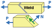
  • To determine the stress in another direction (e.g., normal and parallel to the the plane of a weld);
  • To determine the Maximum Normal Stress or Maximum Shear Stress at a Point (this is useful when an element is subjected to multiple stresses);

» Rotation of a Stress Element
STRESSES of a ROTATED ELEMENT are derived using trigonometry and applying the equilibrium equations. If a Plane-Stress element is rotated by an angle of q, the Transformed Stresses are given by:

sx' =
sx + sy

2
+
sx sy

2
cos(2q) + txysin(2q)
sy' =
sx + sy

2
sx sy

2
cos(2q) txysin(2q)
tx'y' =
sx sy

2
sin(2q) + txycos(2q)
  • Note that q is positive in the counter-clockwise direction.
  • Adding the values for the two normal stresses together, we find that: sx + sy = sx' + sy'
    This is true for any q and is termed Invariance.

» Principal Stresses
PRINCIPAL STRESSES are the Maximum and Minimum Normal Stresses that occur at a point as the set of axes is rotated by angle q. The Principal Stresses are called sI and sII, and occur along the xp-yp axes. The Principal Stresses for a given stress state are given by:

sI =
sx + sy

2
+
sx sy

2
2


+ txy2
1/2


sII =
sx + sy

2
-
sx sy

2
2


+ txy2
1/2


The larger of the two stresses is generally termed sI.

  • The Principal Stresses occur when the stress element has been rotated by an angle of qp, where:
tan(2qp) =
2txy

sx - sy

This equation has two results: angles, qpI and qpII, (90° apart). It is not always obvious which angle goes with which Principal Stress. It is often best to substitute one of principal angles into the general stress-transformation equation for sx'(qp). By doing so, the appropriate angle is matched with the right stress.

  • KEY POINT: When the Normal Stresses are Principal Stresses the Shear Stress is Zero. This can be shown by plugging in either of the principal angles into the general equation for. tx'y'(qp)

» Maximum Shear Stress
The MAXIMUM (In-Plane) SHEAR STRESS occurs when the Principal Stress element is rotated by 45°, and is given by:

tmax =
sI sII

2
=
sx sy

2
2


+ txy2
1/2


  • The angle at which the Maximum Shear Stress occurs is given by:
tan(2qs) =
sx sy

2txy

This equation has two solutions, qsI and qsII, one corresponding to a positive shear stress, the other to a negative shear stress on the new xs-face (defined by qs). It is often best to substitute one of angles into the general stress-transformation equation for tx'y'(qs). By doing so, the appropriate angle is matched with the right shear stress (positive or negative).
It should be noted that qs =qp±45°.

  • KEY POINT: When Shear Stress is maximum, the Normal Stresses are the same and equal to their average. This can be shown by plugging in either of the Shear Stress Angles into the general equation for sx'(qs) or sy'(qs) .