Ex. 7.2.1


| 7.2 Combined Loading Examples Ex. 7.2.1 |


|
|
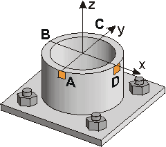
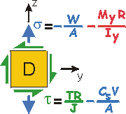
Example 7.2.1 Given: Consider the road sign of Example 2.2.5. The forces, moments, and torque acting at a cross-section near the base of the mast are shown and right (Cut A-A). Req'd: The stress states at the surface of the mast, at Points A, B, C and D. Point A is on the windward side (facing the wind), Point C on the "leeward side" (back side), and Pt. B and D on the left and right sides of the mast. Draw 2-d stress elements as you look from the outside of the mast inward.
|
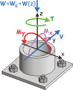
Forces, Moments and Torque acting at Cut A-A. Road Sign |
|
Sol'n: Each load causes the mast to act as a different type of member, for example:
Ix is the Moment of Inertia about the x-axis. Iy is the Moment of Inertia about the y-axis. |
|
Step 2: Consider how each of the loads affects Point A.
| ||||||||||||||||||||||||||||||||||||
|
Point A thus feels three stresses:
What are the stresses at the other points? |
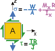
Stress State at Pt. A | |||||||||||||||||||||||||||||||||||
|
(+) means normal stress is TENSILE. Notes on Shear:
| ||||||||||||||||||||||||||||||||||||||||||||||||||
|
|
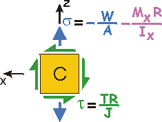 | |||||||||||||||||||||||||||||||||||||||||||||||||
|
 |
 |

|


|