Ex. 2.2.1 | Ex. 2.2.2 | Ex. 2.2.3 | Ex. 2.2.4 | Ex. 2.2.5


| 2.2 Statics Review Examples Ex. 2.2.1 | Ex. 2.2.2 | Ex. 2.2.3 | Ex. 2.2.4 | Ex. 2.2.5 |
|
|
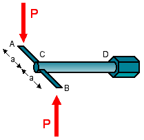
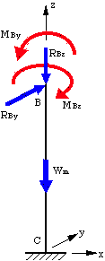
Example 2.2.2 Moment Equilibrium Given: The crane at right is used to transport cargo to and from ocean-going ships. The crane is lifting an object of mass M = 1000 kg. The crane mast has a length of LAD = 30 m, and a mass of mmast = 400 kg. The mast is at an angle of b = 40° from the horizontal, and a = 20°. Note that ABC is a right angle. Req'd: Determine the tension in the cable CD. Sol'n: Create a free-body diagram of the crane mast. Be sure to include all forces acting on the mast, including the weight of the mast itself. To determine the tension in the cable, TCD, all that is necessary is to sum the moments about Point A. |
|
||
|
TCD = kN |
|||
|
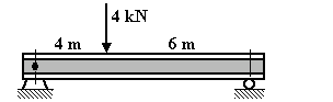
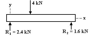
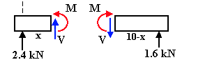
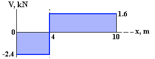
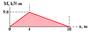
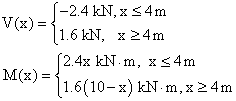
Sol'n: From the FBD of the entire beam, we can find the reaction forces at the beam supports by taking moments about each end (taking counterclockwise moments as positive): SMx=0 = 0SMx=10 = 0 R1 = 2.4 kN R2 = 1.6 kN Check: 2.4 kN + 1.6 kN = 4 kN OK A section of the beam of length x (from the left support) is next isolated and treated as a FBD on which the internal shear force and bending moment are shown in their positive directions (we will get into positive convention stuff later). Applying the equilibrium equations to the FBD gives: S FY = 0 S M = 0 These results are valid for a section of the beam to the left of the 4 kN point load (x=4m). A section of the beam to the right of the 4-kN load is next isolated in the same manner. Equilibrium gives: S FY = 0 S M = 0 These results are valid for sections of the beam to the right of the point load (x=4m). Next, the values for V(x) and M(x) can be plotted as shown at right. Between R1 and the 4-kN point load, the internal shear force has a constant value of -2.4 kN (the shear force acts downward on a positive x-face). To the right of the point load the shear force has a value of +1.6 kN. As we move from x = 0 to the right, the bending moment increases linearly from a value of 0 to 9.6 kN·m at x = 4 m. To the right of the point load, the bending moment decreases linearly from 9.6 kN·m to 0. From this example it is clear that the change in moment is simply negative the accumulated area under the shear diagram [(2.4 N)(4 m) = 9.6 kN-m]. We will cover this subject in much more depth in Chapter 6. |
|

|
|

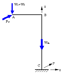
 MA = 0
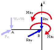